
 MENU
MENU


#08117
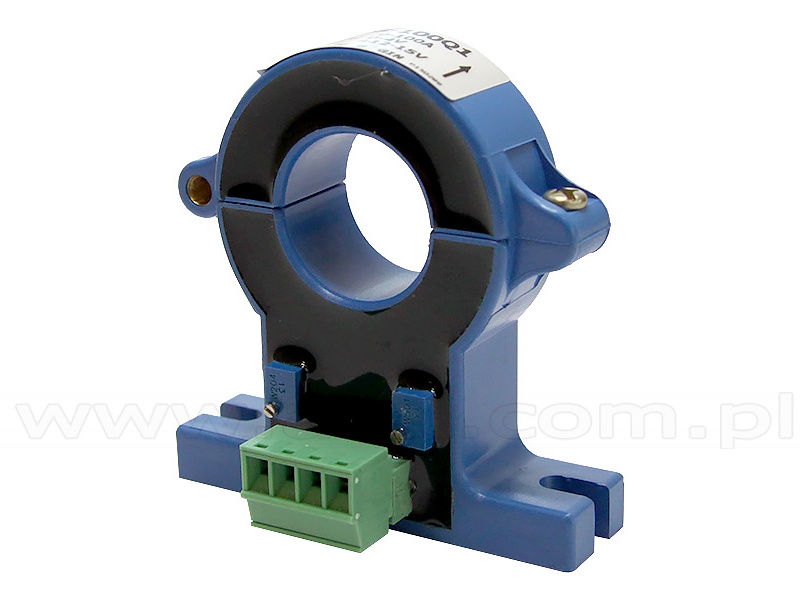
AC current transducer (Vutlan HAT-100Q1)
The clamp sensor enables the measurement of alternating current in the range of up to 100A. Itr can be used together with a VT407 converter (#08116).
| Connection: | |
|---|---|
| Power input | -12V / +12V |
| Outputs | 4 pin terminal |
| Power Consumption | 1 Watt |
| Operating temperature | -10°C ÷ 80°C |
| Operating humidity |
5% ÷ 95%, non-condensing |
| Net weight | 150g |
| Dimensions (LHW) | 68 × 47 x 26 mm / 60 × 61 × 16 mm |
#08116 HAT sensor transducer 0-5V DC (Vutlan VT407)

#08264
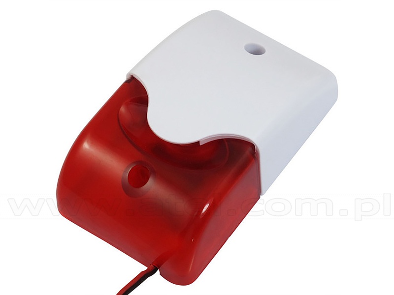
Alarm beacon (Vutlan VT103)
The VT103 indoor optical-acoustic siren is dedicated to work with Vutlan environmental parameters monitoring units.
| Technical specifications | |
|---|---|
| Rated voltage | 12V |
| Sound pressure | 108 dB |
| Tone frequency | 3.8 kHz |
| Flash frequency | 150 / min |
| Net weight | 140g |
| Dimensions (LHW) | 70 x 36 x 56 mm |
#08344
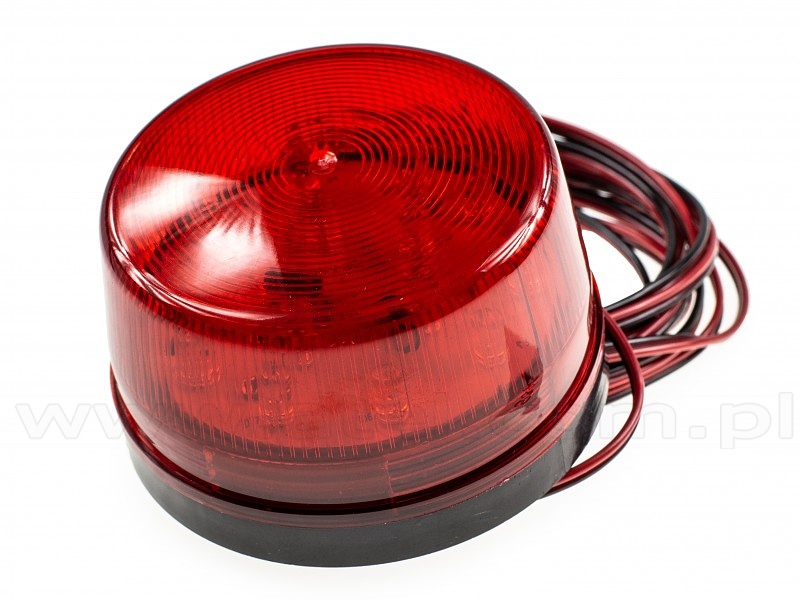
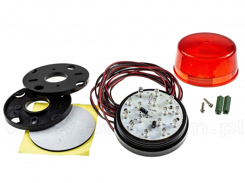
Alarm beacon (Vutlan VT105)
The 12V VT105 indoor optical-acoustic siren is dedicated to work with Vutlan environmental parameters monitoring units.
| Technical specifications | |
|---|---|
| Rated voltage | 12V |
| Flash frequency | 90 / min |
| Net weight | 110g |
| Dimensions (LHW) |
73 x 45mm, cable 3m |
#03880
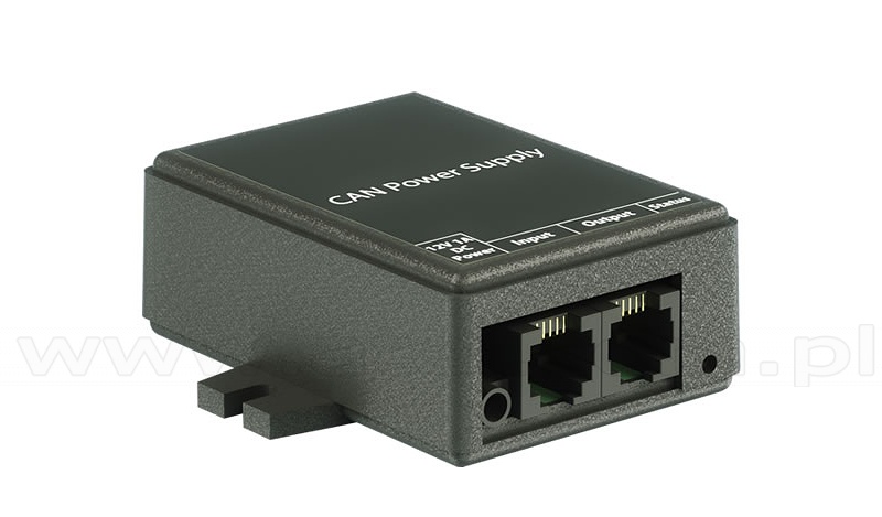
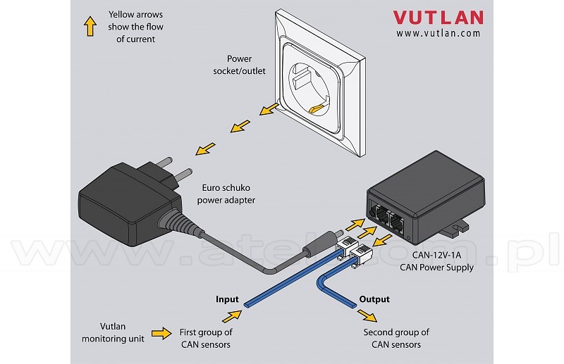
CAN-12V-1A / CAN Power Supply Module
Increases the number of CAN sensors connected on a CAN bus chain. Supplies power for a maximum of 15 additional sensors. Needed only if the number of sensors in a CAN bus chain is greater than 12 sensors.
| Technical specifications | |
|---|---|
| Type | Power supply for CAN bus chain |
| Input | RJ11 6P4C CAN port ⌀3.4/1,35 mm 12V |
| Otuput | RJ11 6P4C CAN port |
| Daisy chain | Allows daisy chain |
| Max. q-ty of CAN sensors powered | 15 |
| LED indicators | Green (Status On/Off) |
| Environmental | |
| Working temperature range | −40 °C to +100 °C |
| Humidity operating range | 0-95% RH |
| Mechanics | |
| Dimensions | 68 x 67 x 26,2 mm (LxWxH) |
| Packaging weight | 190g |
| Mounting options |
Desktop, Wall mount, Indoor |
#08390
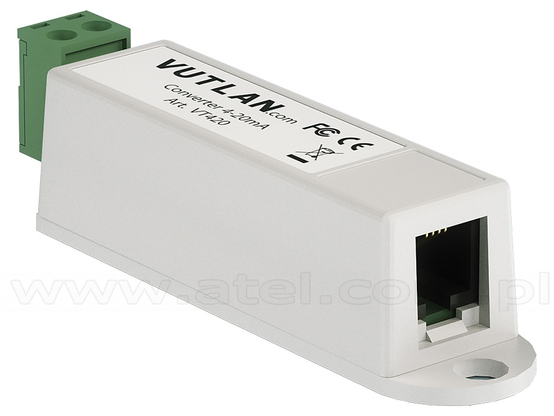
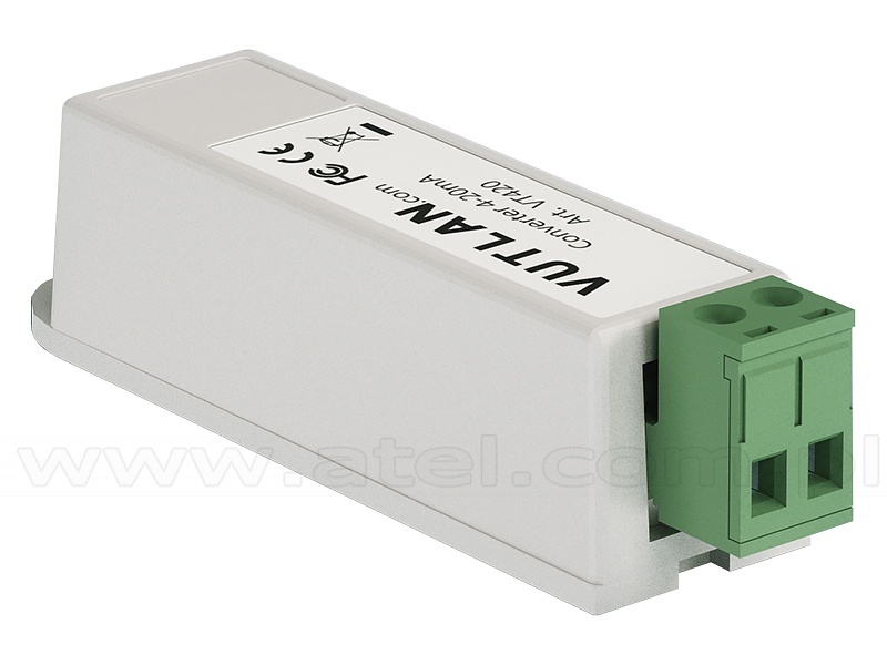
Converter 4-20mA (Vutlan VT420)
Converter of current loop 4-20mA is used for measurement of constant current on 4-20mA outputs of sensors and converting data into a IP monitoring system format. The system interface allows you to assign the sensor and to introduce the function data conversion.
Galvanic isolation of 3 kV between I/O is used in a receiver.
Galvanic isolation of 3 kV between I/O is used in a receiver.
#08186
Dry contacts board IN/OUT (Vutlan VTX40)
A complementary module for VT900 and VT960 DC master units.
| Technical specifications | |
|---|---|
| Dry contacts |
x32 dry contact inputs, x8 isolated dry contact outputs |
| Connection | BH-10 |
| Supply includes |
BH-10 bus cable, x8 terminals (6P 3.5mm), x2 terminals (8P 3.5mm), x5 screws |
| Dimensions (LHW) | 241 x 35 x 11 mm |

#08235

Dry contacts module (Vutlan VT16)
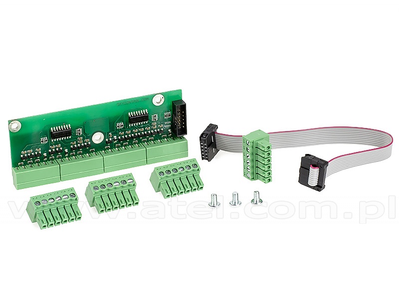
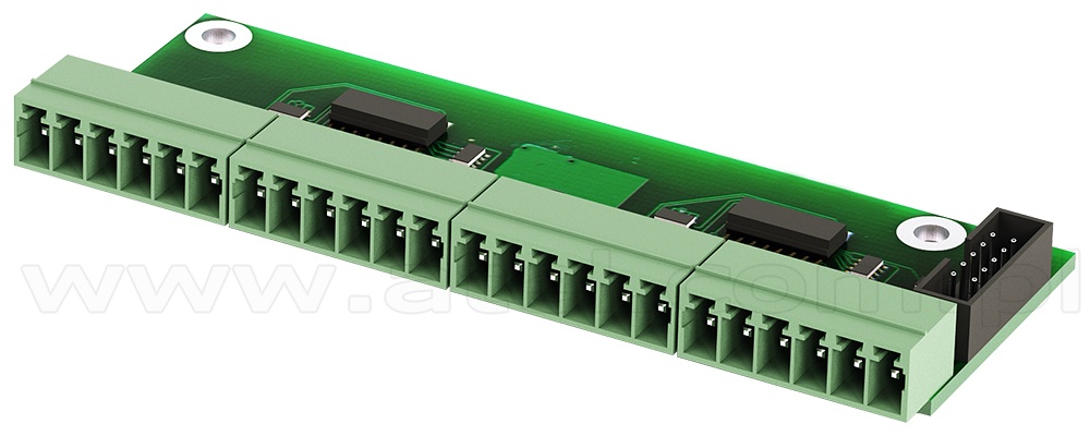
Complementary module for moin units, can be connected to 16 dry contacts.
Dedicated for SC8100, VT8101, VT8110, VT800.
Dedicated for SC8100, VT8101, VT8110, VT800.
| Technical specifications | |
|---|---|
| Dry contacts | 16 |
| Contact outputs | 3.5 mm |
| Features | |
| Installation | On the PCB there are 3 mounting holes for fastening to the surface using screws 3 mm inside of any master unit. |
| Connection | Jack IDC2-10 is connected to IDC2-10 input of master unit. Determination of PCB's type and connection occur automatically. Monitoring system allows connection of up to 16 dry contacts. |
| Supply includes |
PCB, 10-wired IDC2 cable (10cm), 3 screws M3. |
| Net weight | 80g |
| Dimensions (LHW) | 70x10×25mm |
#08916
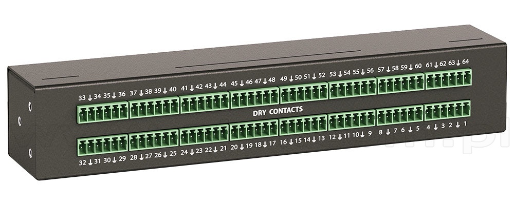
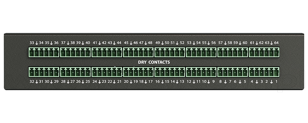
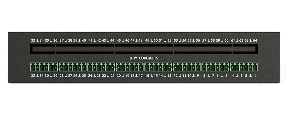
Dry contacts unit (Vutlan VT440)
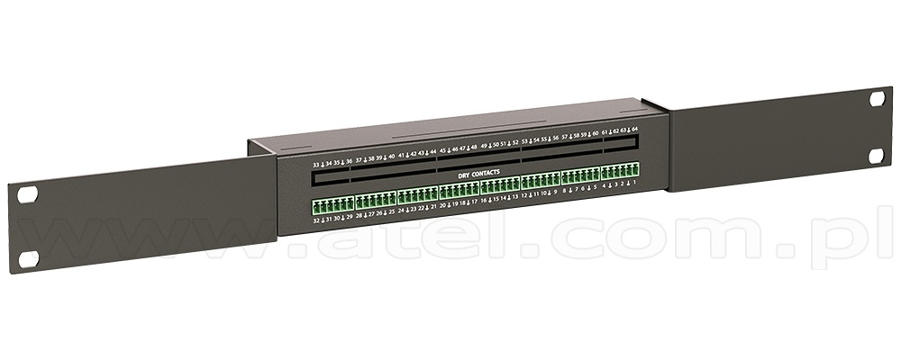
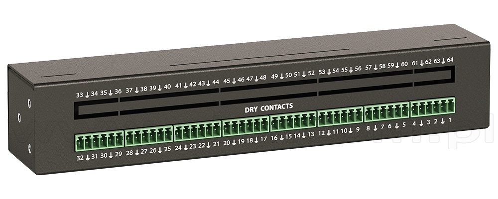
Allows to increase the number of dry contacts connected to any Vutlan monitoring unit. Adds 32 dry contacts (or 64 with VT32 module). Can be connected to any CAN port.
| Number of dry contacts | 32 - 64 |
|---|---|
| Contact outputs | 3.5mm |
| Max contact distance | 500m |
| Number of CAN ports |
2 (1 input, 1 output) |
| Mounting |
The unit includes two 19" mounting angles for mounting inside the rack. Alternatively, there are 2 mounting holes on the bottom of the case for fastening on the wall. Fasten the unit, connect CAN inputs to the input of the previous CAN unit or of the monitoring unit. The red LED lights up. Match the bus terminators of the CAN units. Switch terminator TR in ON position on the monitoring unit and on the last CAN unit, TR on intermediate CAN units are in Off (1,2) position. Maximum 8 CAN units, sensors and/or devices can be on one CAN bus. |
| Inventory |
Unit, 3-pair shielded patch cable RJ-12 2 m length, screw 3.5 x 16 mm, fastener 2-sided, rubber feet, 19" mounting angles. |
| Net weight | 0.5 kg |
| Dimensions (LHW) | 215×40×40mm |

#08116
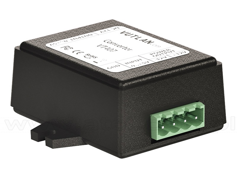
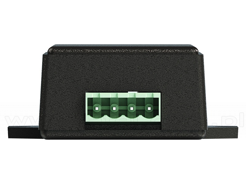
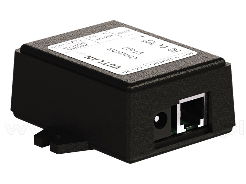
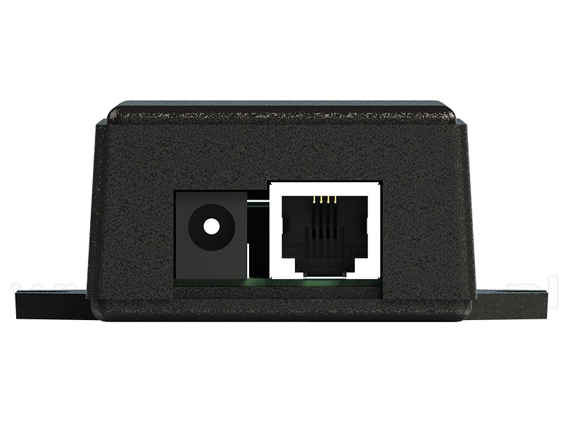
HAT sensor transducer 0-5V DC (Vutlan VT407)
The transducer is used together with HAT-100Q1 current transducer.
| Power input |
12V DC, 1A |
|---|---|
| Input | RJ-12 / RJ-11 |
| Power Consumption | 100mW |
| Operating temperature | -10°C ÷ 80°C |
| Operating humidity |
5% ÷ 95%, non-condensing |
| Net weight | 150g |
| Dimensions (LHW) | 68 × 47 x 26 mm |
| Max distance | 50m |
#08117 AC current transducer Vutlan HAT-100Q1
#03105
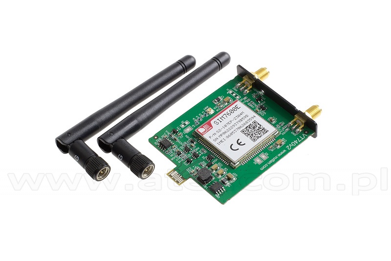
Internal LTE, GPS modem (Vutlan VT740)
4G LTE slot modem for Vutlan monitoring units. Allows to receive and send SMS messages. Provides Ethernet over 4G LTE. Power-cycling is an embedded function.
Can be used together with VT335t, VT825t/VT825tt, VT855t/VT855tt & VT604/VT608.
Antennas included.
Can be used together with VT335t, VT825t/VT825tt, VT855t/VT855tt & VT604/VT608.
Antennas included.

Page 4 of 8
|


